
Laser Data Matrix Marking on Metal: Cell Size, Contrast and Verification
Laser Data Matrix marking on metal is not complete when a code merely looks square and dark. A production code must encode the correct data, fit the available area, survive the downstream process and remain readable by the specified scanner. That result depends on the relationship between cell size, marking contrast, surface texture, laser spot, focus, code geometry, illumination and verification rules.
This guide is for process engineers, quality teams and buyers planning direct part marking on stainless steel, carbon steel, aluminum, anodized parts, plated components and other metals. It does not prescribe one universal laser recipe. The supplier and customer should build a process window from real samples, then lock the code format, fixture, marking recipe and verification method before production approval.
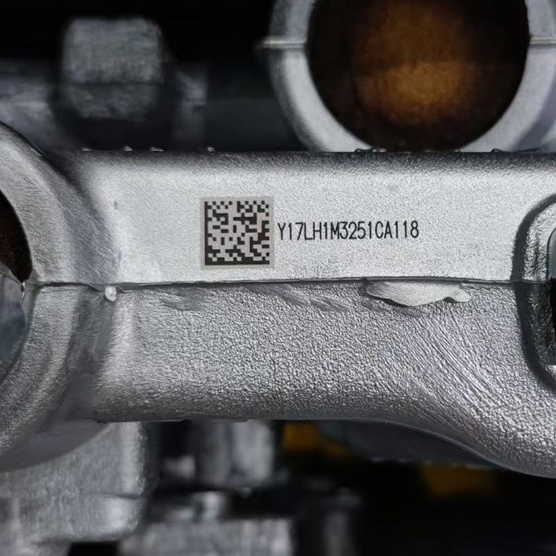
Data Matrix Decisions That Must Be Frozen
| Item | Why it matters | Acceptance evidence |
|---|---|---|
| Encoded data | Controls symbol size and traceability meaning | Decoded value matches source record |
| Cell size | Must be large enough for the laser process and scanner optics | Measured modules and stable decode on approved scanners |
| Quiet zone | Separates the symbol from text, edges and surface features | Drawing and fixture keep the area clear |
| Marking mechanism | Annealing, color change or ablation produces different contrast and durability | Approved sample after downstream processes |
| Verification method | A phone camera is not a production verifier | Defined verifier, lighting, standard and grade threshold |
| Reject flow | Prevents an unreadable or duplicate code from escaping | PLC/MES OK/NOK and rework logic tested |
Cell Size Is a Process Limit, Not a Design Preference
A Data Matrix symbol is built from individual light and dark cells, often called modules. When cells become too small relative to the focused spot, positioning accuracy, material response and scanner resolution, their edges merge or vary. The code may decode under ideal lighting but fail when focus shifts, the surface changes or the scanner is moved to the real production distance. The correct minimum cell size is therefore demonstrated by process capability, not copied from a drawing template.
Start with the encoded data and required symbology. More characters usually require more cells. Then compare the available marking area, quiet zone, neighboring text, part edge and fixture tolerance. If the available area is too small, the solution may be to shorten the encoded data, move descriptive data to the database, increase the marking area or choose a scanner with suitable optics. Making every cell smaller should be the last option, not the first.
During sample testing, measure code dimensions and evaluate several positions in the laser field, not only the center. A large field lens can change spot behavior and edge performance. If parts have height variation, test the upper and lower focus limits. Curved surfaces need additional care because cells can distort and illumination can reflect unevenly.
How Metal Surface and Marking Mechanism Create Contrast
On stainless steel, a controlled color change or annealed appearance may create a dark symbol without deep material removal. On anodized aluminum, selective ablation can expose a contrasting layer. On coated or plated parts, the laser may remove or modify the top layer. Bare aluminum, copper and reflective metals can require a different source or parameter window. In each case, the “dark” and “light” cells are produced by a physical surface response that must remain stable across batches.
Contrast is influenced by focus, power, pulse behavior, frequency, scan speed, hatch strategy, number of passes and surface preparation. Too little energy can leave weak cells. Too much can melt boundaries, create glare, raise debris or alter surrounding material. A visually black mark is not automatically the best scanner mark; excessive gloss or irregular texture can reduce usable contrast under production lighting.
Surface variation matters. Machining lines, blasting, oil, oxide, paint thickness and anodized color can all change the result. The sample set should include normal variation from multiple lots. If cleaning is required before marking, define the cleaning method as part of the process. An operator wiping some parts more aggressively than others is not a controlled production step.
Focus, Fixture and Field Calibration
Stable focus begins with a stable datum. The fixture must locate the marked surface at a repeatable height and position. A part that rocks or is loaded against the wrong edge can shift the code, change cell shape or move the surface outside the approved focus window. For mixed models, recipe selection and fixture identification should prevent an operator from applying the wrong code layout.
Laser field calibration should be checked across the usable marking area. A code marked near one corner should not become stretched or skewed compared with the center. The FAT should include a calibration pattern or measured reference, and maintenance should define when calibration is rechecked after lens, scanner or workstation changes. If the mark uses a rotary axis, seam placement and angular synchronization also require verification.
Verification: Decode Is Not the Same as Grade
A handheld scanner answering with the correct text proves that one code decoded once. It does not show whether the process has adequate margin. A verification system evaluates characteristics such as contrast, modulation, cell geometry, fixed-pattern damage and quiet-zone quality under defined conditions. The applicable standard, lighting setup and grade threshold depend on the customer and industry; these must be specified rather than assumed.
Use the same verifier model and setup agreed for acceptance, or document the correlation between laboratory and line scanners. Fix the scanning distance, angle, lighting and exposure. Record both the decoded data and quality result. When a grade is below threshold, the system should hold or reject the part and save enough information to diagnose the failure. Re-marking is not always safe because a second pass can damage cell geometry or create a duplicate record.

Closed-Loop Production Data
In an automated station, the PLC or MES should provide or confirm the data, select the correct recipe, trigger marking and receive a completion signal. The scanner then reads the code and returns OK/NOK. A complete traceability record can include the source serial number, timestamp, recipe revision, machine ID, decoded value and verification result. The laser marking machine with MES integration guide explains the data handshake and rework questions in more detail.
Duplicate prevention is essential. The system should know whether a serial number was already marked, whether a failed part is being reworked and who authorized a manual override. Operators should not be able to type arbitrary production codes when the approved path is database driven. Network loss, scanner timeout and database delay need visible recovery states instead of silent continuation.
Common Failure Patterns and Corrective Direction
- Cells merge: increase usable cell size, review spot size, focus, energy and hatch strategy.
- Weak contrast: review surface preparation, marking mechanism, parameters and illumination.
- One side decodes poorly: check field calibration, focus tilt, part height and scanner angle.
- Code looks good but grades low: inspect modulation, glare, texture and verifier configuration.
- Intermittent wrong data: inspect database handshake, race conditions, recipe selection and duplicate control.
- Grade falls after coating or cleaning: include the downstream process in sample approval and durability testing.
RFQ and FAT Checklist
- Provide material, finish, surface variation and downstream processes.
- Provide exact encoded data examples and maximum data length.
- Define the available marking area, quiet zone and required text around the code.
- Name the verification standard, verifier, lighting and minimum acceptable grade.
- Define cycle time including load, mark, scan, data save and reject handling.
- Test minimum and maximum focus height, field positions and normal material lots.
- Demonstrate wrong-part, wrong-recipe, duplicate-code, network-loss and scanner-failure handling.
- Approve golden samples and retain parameter, fixture and verifier revisions.
CNMarking can review a real part, code content and scanner requirement before recommending a laser configuration. See the MOPA laser and scanner integration example, or send the project details for a sample test.
Frequently Asked Questions
What is the smallest Data Matrix cell a laser can mark on metal?
There is no universal value. The usable minimum depends on the focused spot, material response, field position, focus tolerance, scanner optics and required verification grade. It must be demonstrated with real samples and the agreed verifier.
Can I verify a metal Data Matrix code with a phone?
A phone may help during a quick visual check, but it is not a controlled production verifier. Acceptance should use an agreed scanner or verifier, defined lighting, a named standard and a recorded threshold.
Should a Data Matrix code be deep engraved?
Not always. Required durability, coating, abrasion and industry rules determine the marking mechanism. Deep engraving can reduce edge quality or cycle time; a controlled contrast mark may be better when it survives the actual process.
Why does a code scan in the lab but fail on the line?
Common causes include different lighting, distance, angle, focus, surface batches, motion, contamination or scanner settings. Correlate the lab verifier and production scanner, then test the full process window.
Can the machine automatically reject unreadable codes?
Yes, when scanner output, PLC/MES logic and physical reject handling are designed as a closed loop. The FAT should test OK, NOK, timeout, duplicate and network-failure paths.