
Copper Part Marking: Scribe vs Dot Peen vs Fiber Laser
Copper part marking is difficult for a simple reason: the material is conductive, reflective, often relatively soft, and frequently used in parts where appearance and geometry both matter. A method that creates a strong mark on carbon steel can produce shallow contrast, burrs, local deformation, or inconsistent characters on copper. The correct choice is therefore not “which marking machine is strongest?” It is “which process creates the required identification without damaging this particular part?”
This guide compares scribe, dot peen and fiber laser marking for busbars, terminals, electrical contacts, copper plates, brass fittings, heat-exchanger components and other conductive metal parts. It focuses on the questions a process engineer or buyer can verify: mark depth, visual contrast, deformation risk, cycle time, noise, consumables, fixture needs and code readability. Exact machine settings cannot be selected from a material name alone. Alloy, temper, coating, thickness, shape and the customer acceptance standard must be confirmed with samples.
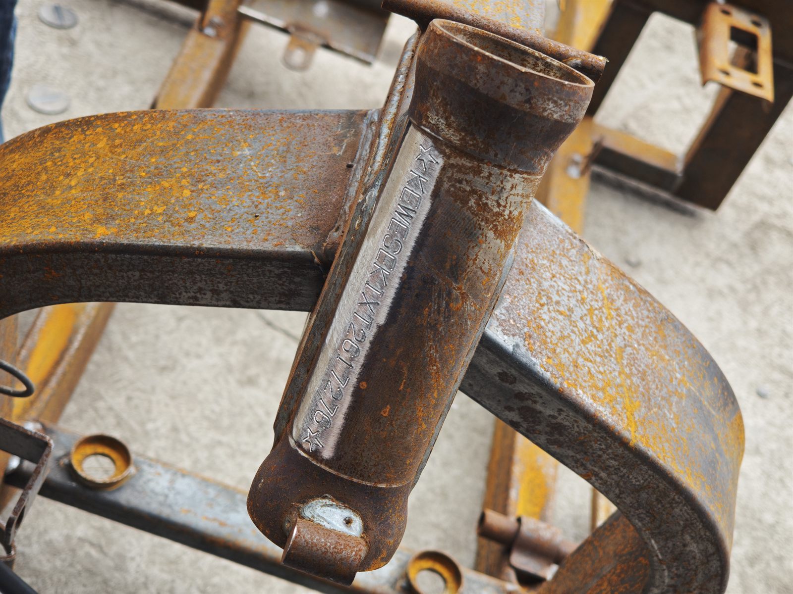
Scribe vs Dot Peen vs Fiber Laser at a Glance
| Decision factor | Scribe | Dot peen | Fiber laser |
|---|---|---|---|
| Typical mark | Continuous engraved line | Series of controlled indentations | Surface color change, ablation or engraving |
| Depth potential | Useful for continuous, tactile characters | Useful for permanent indented characters | Ranges from contrast marking to multi-pass engraving |
| Deformation risk | Depends on stylus force, support and wall thickness | Depends on impact energy, dot density and backing | Mechanical force is low; heat and reflectivity must be controlled |
| Visual character | Clean, continuous strokes | Dotted industrial appearance | Fine text, logos and machine-readable codes |
| Production environment | Needs rigid positioning and stylus access | Portable or integrated formats are available | Needs correct guarding, extraction and focus control |
| Best reason to select | Continuous deep text with low dot-peen noise | Robust permanent IDs on supported parts | Fine content, variable data and non-contact processing |
Start with the Part, Not the Machine
Before comparing technologies, define the part. Record the copper grade or alloy, temper, wall thickness, surface finish, plating or coating, available marking area and whether the opposite side is cosmetically visible. A thick copper busbar supported on a flat nest behaves very differently from a thin stamped electrical contact. Brass also behaves differently from high-purity copper, even though both may be grouped under “copper parts” in a request for quotation.
Next define the mark. Plain text and a short serial number tolerate a wider process window than a small Data Matrix code. If the mark must remain readable after plating, painting, cleaning or abrasion, the required depth and downstream process must be stated. If an optical scanner will verify the code, “looks clear to an operator” is not an acceptance test. The scanner, lighting, cell size and grade threshold become part of the process specification.
When Scribe Marking Fits Copper Parts
Scribe marking draws a carbide or diamond stylus through the surface to create a continuous groove. It can produce characters that look cleaner than a dotted mark and may be preferred on nameplates, brass valves, fittings and parts where continuous strokes are easier for operators to read. Because the stylus remains in contact with the workpiece, the fixture must resist lateral movement. Thin parts need backing close to the marked area so the stylus does not flex or pull the material.
Key variables include stylus geometry, applied force, travel speed, number of passes, character size and surface condition. More force is not automatically better. Excess force can raise burrs, drag a soft surface, distort a thin section or shorten stylus life. A useful sample test checks the entrance and exit of each stroke, corner quality, depth consistency, burrs and part movement. For suitable projects, review the scribe marking machine range and send a drawing showing the supported marking area.
When Dot Peen Marking Fits Copper Parts
Dot peen uses a controlled stylus impact to form characters from a pattern of indentations. It is widely used for industrial serial numbers because the mark is tactile and does not depend on ink or labels. On a thick copper or brass component, dot peen can be a practical option when permanent identification is more important than a perfectly smooth visual finish. Portable heads can also reach installed parts that cannot be placed under a stationary laser.
The risks are predictable and testable. Soft copper may show displaced material around dots. Thin terminals can dish or bend if they are not backed. Small characters can close up when dot density or impact energy is too high. The fixture should support the marked zone, not only hold the outside edge of the part. Start with the lowest energy that produces an acceptable mark, then adjust dot spacing, speed and passes while measuring deformation. The pneumatic dot peen marker is one route when the application needs deeper mechanical identification, but the final head, stylus and fixture must match the real part.
When Fiber Laser Marking Fits Copper Parts
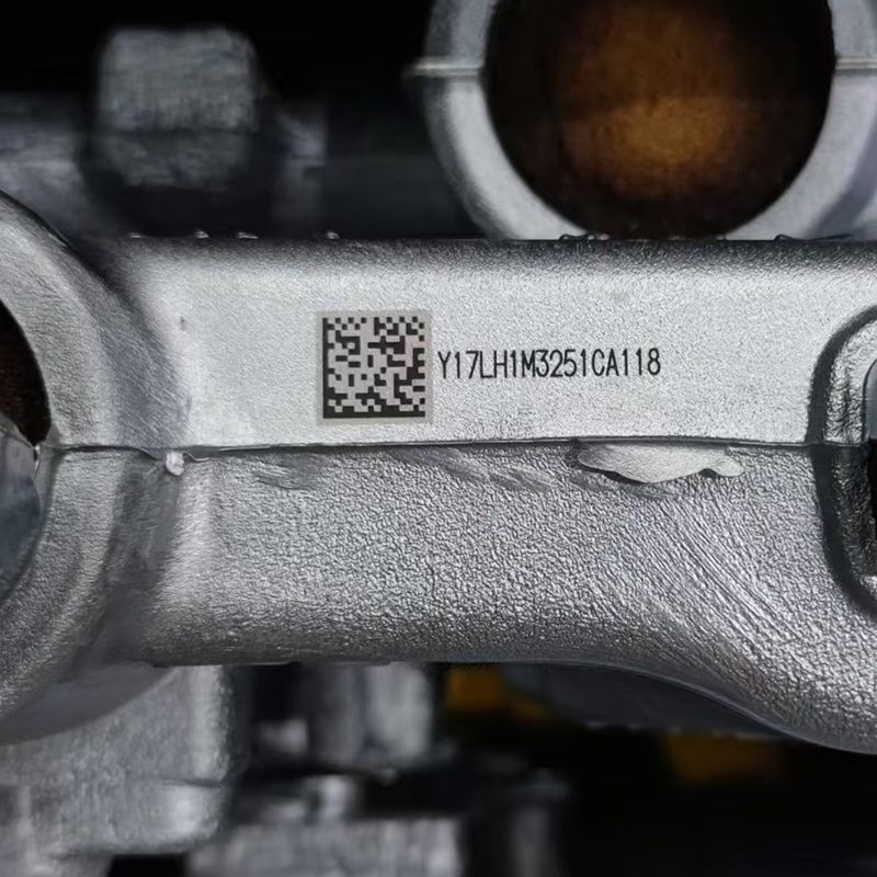
Fiber laser marking is non-contact, which removes stylus force and tool wear from the process. It supports fine text, logos, serial numbers, barcodes and Data Matrix codes. It also connects naturally to CSV files, databases, PLC triggers and scanner verification. These advantages make laser attractive for electrical components and automated traceability, especially when the part is too delicate for impact marking.
Copper reflectivity and heat conduction narrow the parameter window. A visible mark may require controlled surface modification, ablation of a coating, or multi-pass engraving. A conventional fiber source may work for some alloys and finishes, while a MOPA, green or UV process may offer a better window for another. That selection cannot be guaranteed from a web page. Pulse behavior, spot size, focus, scan speed, hatch strategy and heat accumulation must be tested. The goal is not maximum power; it is stable contrast or depth without excessive melting, discoloration outside the mark, edge rounding or damage to a functional contact surface.
For a first evaluation, the standard fiber laser marking machine provides a useful reference format. If black contrast, very fine features or sensitive coatings are involved, include that requirement in the sample request so the supplier can compare source types instead of quoting only wattage.
Fixture, Focus and Production Flow
Most unstable copper marks are not caused by the marking head alone. A part that rocks in the fixture changes focus and character position. A thin piece without backing deforms during mechanical marking. An operator who can load the part in two orientations creates traceability risk. The fixture should provide a repeatable datum, poka-yoke orientation, support near the mark and clearance for the marking head or laser field. For families of parts, changeable nests should preserve the same datum strategy.
Cycle time must include loading, clamping, data entry, marking, verification and unloading. Mechanical marking may be fast for short text but slower for dense codes. Laser may mark complex content quickly, but focus adjustment and guarding can dominate manual work. Automated cells should define part-present signals, recipe selection, duplicate-code prevention, mark-complete feedback, scanner result and reject handling. Compare the full work cycle rather than the advertised marking speed.
Sample Test and Acceptance Checklist
- Provide material grade, temper, finish, coating and thickness.
- Send a drawing with the marking zone, protected surfaces and fixture datums.
- Provide the real text or code, minimum character or cell size and variable-data format.
- State the required depth, contrast, scanner grade and downstream processes.
- Measure distortion, burrs, heat-affected appearance and mark position on several samples.
- Test after cleaning, plating, painting, abrasion or handling when those steps are part of production.
- Approve a golden sample and record the machine recipe, fixture and inspection method.
A responsible supplier should show the trade-off between methods, not force every copper part into one machine category. Send part photos and acceptance criteria through the CNMarking contact page to request a sample-marking review.
Frequently Asked Questions
Can a fiber laser mark pure copper?
It may be possible, but reflectivity, heat conduction, surface condition and the required result all affect the process window. A sample test should compare contrast, edge quality, heat effect and repeatability. Do not approve a machine from wattage alone.
Will dot peen deform a copper busbar?
A thick, well-supported busbar may accept dot peen marking, while a thin or unsupported part can bend or show material displacement. Backing, impact energy, stylus, character size and dot density must be evaluated on the real part.
Is scribe marking quieter than dot peen?
Scribe usually produces a continuous scratching sound rather than repeated impacts, so it can be perceived as quieter. Actual workplace noise depends on the machine, enclosure, part resonance and fixture. Measure it in the intended environment.
Which method is best for a Data Matrix code on copper?
Laser is commonly preferred for fine machine-readable codes because it is non-contact and supports precise variable data. The code still needs an approved cell size, contrast method, scanner setup and verification threshold.