
K3 Dot Peen Marking Settings: Depth, Speed, Pressure and Fixtures
K3 users usually do not fail because they forgot a menu item. They fail because they try to force one generic setup across different metals, surface finishes, part rigidity, and code requirements. A readable mark on a flat mild-steel bracket does not prove the same settings will work on a coated housing, curved tube, or harder alloy part.
This guide explains how to tune K3 dot peen marking settings for industrial B2B work without inventing universal numbers. The right result comes from matching depth target, speed, contact pressure, and fixture stability to the real workpiece, then checking readability, cycle time, downtime risk, and operator safety before release.
If you need to compare machine families first, review the dot peen and scribe marking machine range. If you already have sample parts and want the correct route for deep marks, VIN-style traceability, or fixture design, contact CNMarking with the material, mark content, available area, and expected output.
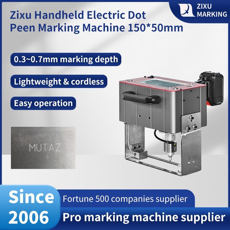
What settings means on a K3 dot peen marker
The K3 is an electric dot peen marker, not a pneumatic unit that depends on plant air pressure. In practical setup discussions, buyers still use the word pressure, but on a K3 that usually means how firmly the marking head is seated on the part, how stable the stylus contact is, whether the operator is holding the body square to the surface, and whether the fixture prevents bounce or drift during marking.
- Depth is the finished indentation and durability target, not a fixed menu number copied from another part.
- Speed is the production tempo you can keep while still holding readable characters and stable dot shape.
- Pressure is the real contact condition between stylus, head, fixture, and workpiece surface.
- Fixture quality decides whether the same settings stay stable over a full shift or collapse into rework and downtime.
Preparation before changing any K3 marking setting
- Confirm the workpiece material, hardness range, coating condition, and whether the marking zone is flat, curved, oily, plated, or painted.
- Define the output requirement first: human-readable text, VIN-style code, serial number, logo, QR, or Data Matrix.
- Check the available marking area, part support points, and whether magnetic or mechanical fixturing is stable enough for repeated contact.
- Inspect stylus wear, guide movement, fasteners, cable condition, and whether the head sits squarely on the workpiece.
- Prepare acceptance criteria before the trial: readability, depth consistency, cycle time, downstream coating or assembly fit, and rework tolerance.
Depth setting boundaries: start from the mark requirement, not from habit
Deeper is not always better. A mark that is too light may fail durability or scanner readability, but a mark that is too aggressive can distort thin sections, create burr around the dot pattern, or slow the job enough to damage throughput. The right depth target depends on the material, the required service life of the mark, and whether the next process is painting, coating, cleaning, or cosmetic inspection.
- Thin or cosmetic parts: keep depth conservative and confirm that the backside, edge, and surrounding finish are not affected.
- Harsh-environment traceability: verify that the mark stays readable after coating, handling, corrosion exposure, or cleaning.
- Curved or unsupported parts: confirm depth consistency at the beginning and end of the line, not only on the easiest sample.
Speed setting boundaries: cycle time only counts when readability survives
Buyers often ask how fast the K3 should run, but the correct answer depends on character size, dot density, material response, fixture rigidity, and whether the operator is freehand or working on a locator. A fast setting that causes incomplete dots, ragged edges, or frequent second-pass correction is not faster in production. Measure the full operation: loading, head positioning, marking, visual check, and any repeat pass.
Use trial marks to find the fastest stable setting that still keeps code edges, line spacing, and scanner readability within the acceptance target. If speed only works on the first sample but falls apart after head repositioning or part variation, the real bottleneck is fixture or contact stability, not the menu value.
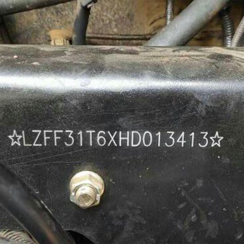
Pressure and head contact: the hidden source of unstable K3 marks
On a K3, unstable contact pressure shows up as shallow starts, uneven dot rhythm, extra vibration, or marks that look acceptable on one side and weak on the other. This usually comes from operator angle, part movement, unsupported thin walls, magnet mismatch, or a locator that does not hold the head squarely to the part.
- For flat parts: check that the head is not rocking during marking.
- For curved parts: confirm the contact point stays aligned across the full character string.
- For handheld work: train the operator on approach angle, grip, and how long to hold the head stable after positioning.
- For repeat jobs: move from hand feel to a guided fixture or stop block before increasing output targets.
Fixture selection: when the correct fixture saves more than the correct setting
If the part is awkward, oily, curved, hot, or already assembled in a larger structure, the fixture usually matters more than one extra parameter adjustment. A good fixture keeps the mark location repeatable, reduces operator correction, and lowers stylus and rework losses. For magnetic holding, confirm the base material and real contact area. For nonmagnetic or coated surfaces, use a mechanical locator instead of forcing an unstable hold.
When a buyer asks for deeper marks and faster cycle time at the same time, the first answer should often be a better locator or support method, not a more aggressive setting change.
Step-by-step K3 tuning workflow for production parts
- Clean the marking zone enough to remove oil, loose rust, heavy coating residue, or burr that would change head contact.
- Clamp or support the real production part, not only an ideal flat coupon.
- Start from the supplier baseline for the material family and mark type, then change one parameter family at a time.
- Check dot shape, line continuity, edge stability, and readability after each change.
- Run a short repeat batch instead of one success sample so you can see drift, operator fatigue, or fixture looseness.
- Record which setting change solved which symptom. That short log is more useful than copying a generic parameter sheet.
Quality checks after the first acceptable K3 sample
- Verify character height, spacing, and code placement against the drawing or traceability rule.
- Check whether the mark remains readable after wiping, handling, and the next process step.
- Inspect surrounding finish for raised burr, excessive indentation, slipping, or cosmetic damage.
- Confirm repeatability across multiple parts, not just one easy sample.
- For coded marks, test scanner readability with the real verification device used on the line.
Downtime and safety: do not optimize settings while ignoring operator risk
Most avoidable downtime comes from worn styli, loose fixtures, repeated re-marking, and operator correction loops. Build a simple preventive check into the shift start: stylus condition, guide smoothness, fixture hold, cable strain, and clean support surfaces. Stop the trial if the head starts bouncing, the fixture loosens, or the operator needs repeated repositioning to finish one mark.
- Safety: keep hands clear of the stylus path, support the part before contact, and do not chase unstable marks on a moving or poorly supported workpiece.
- Downtime control: replace worn consumables before troubleshooting software menus, because bad contact often looks like a settings issue.
- Process discipline: save only settings that survive repeated parts under normal operator handling.
When K3 is the right route, and when you should escalate to another setup
The K3 is a strong fit when you need portable, electric dot peen marking with repeatable permanent marks on metal parts and a larger handheld window than the basic small-format model. If the job needs much higher throughput, more rigid automated loading, or easier operation on difficult geometries, it may be better to compare a different handheld fixture, a pneumatic dot peen platform, or a bench or in-line marking station.
CTA: match K3 settings to the real part, not to a copied parameter sheet
If you need help setting depth, speed, contact pressure, or fixturing for a K3 project, send CNMarking the material, part photo, mark content, available area, and daily output target. That makes it possible to recommend the right machine route and sample-test plan instead of guessing from a generic settings screenshot.