
Troubleshooting Low Marking Depth in Pneumatic Dot Peen Marking Machines
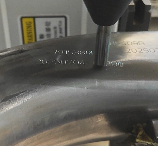
When the pneumatic dot peen marking machine fails to achieve the expected marking depth, the resulting chain reaction will soon be manifested on the production line: the two-dimensional Data Matrix code cannot be scanned and recognized, the characters are completely covered during the subsequent powder spraying process, and even directly result in the workpiece being judged as unqualified in the quality system audit.
In the vast majority of industrial applications, the insufficient or inconsistent marking depth is not caused by major equipment failures, but rather by details such as the gas supply system, wear of the marking needle/mechanical components, alignment of the clearance space, and the timing settings of the software. This guide provides you with a systematic troubleshooting framework to help you quickly identify and resolve the problem of insufficient marking depth.
Quick Diagnostic Matrix for Dot Peen Marking Depth
Use this quick diagnostic table to narrow down the root cause before opening the marking head or adjusting system parameters.
| Symptom / Inspection Area | Likely Root Cause | Recommended Corrective Action |
| Air pressure fluctuates during marking | Restricted air line, clogged filter, or low supply | Clean FRL filter; increase supply line diameter; set static pressure to 0.5 – 0.6 MPa. |
| Characters are faint, wide, or blunt | Worn, chipped, or dulled carbide stylus tip | Inspect stylus point angle (90 degrees or 120 degrees); regrind or replace the stylus pin. |
| Inconsistent depth across flat parts | Incorrect standoff distance or loose Z-axis fixture | Reset clearance gap to 2 – 4 mm; tighten fixture bolts to eliminate play. |
| Impact force drops at high speed | Slow solenoid valve response or internal carbon buildup | Clean solenoid valve port; replace valve core if switching delay exceeds limits. |
| Dots are shallow despite high air pressure | Speed set too fast in controller software | Lower marking speed; increase dot dwell time / pulse width in settings. |
5 Root Causes of Low Marking Depth
If your machine is not penetrating metal to the required specification, inspect these five critical areas in order.
Step 1: Insufficient Air Pressure & Dynamic Pressure Drop (0.4 – 0.6 MPa)
- Front-end compressor gas supply -> Focus on testing the dynamic pressure drop of the FRL pneumatic triplex unit at the moment of marking.
- FRL filter pressure regulating valve -> Compare and verify the difference between the static pressure and the dynamic working pressure.
- High-frequency electromagnetic valve -> Check the millisecond-level response speed of the valve and the smoothness of exhaust.
- Mark the head cylinder/needle sleeve -> Verify and calibrate the 2-4 mm gap between the needle tip (Stand-off Distance).
- Check the FRL pneumatic triplex unit: Check the status of the filter – regulator – oil mist device (FRL). If the 5-micron (5 μm) filter element becomes clogged, it will cause extremely high resistance, resulting in a sudden drop in dynamic pressure during continuous marking and a reduction in impact force.
- Calibrate the set supply pressure: Precisely set the equipment’s dynamic working pressure to 0.4-0.6 MPa (60-90 PSI). When the working pressure is lower than 0.4 MPa, the descent speed of the impact needle and the impact energy will significantly decrease.
- Check the diameter of the air source hose: Using a hose with an inner diameter smaller than 8 mm or an excessively long supply hose will cause severe flow throttling. It is recommended to replace the hose near the marking head with a large-diameter, short-range dedicated pneumatic hose to ensure instantaneous high-flow supply.
Step 2: Worn Carbide Stylus Pin & Fatigue Return Spring
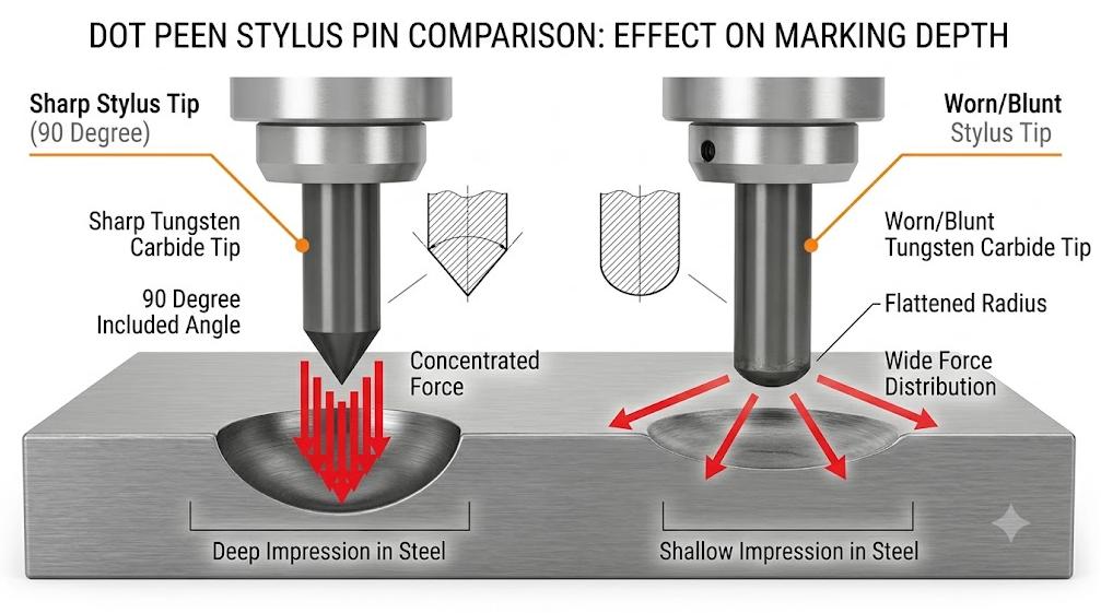
The tungsten carbide marking needle needs to withstand millions of high-frequency and high-strength impacts. Over time, the physical wear of the needle tip will change the geometric shape of the impact contact surface, thereby significantly absorbing and dissipating the impact energy.
- Check and correct the geometry of the needle tip: Remove the marking needle and use a magnifying glass to observe the condition of the needle tip. A rounded or chipped needle tip will disperse the impact force over a larger surface area, resulting in a significant decrease in the marking depth. The tungsten carbide needle tip should be re-ground to the factory-set angle (usually 90° for deep structure marking; usually 120° for thin sheet marking).
- Testing the performance of the internal return spring: If the return spring undergoes fatigue failure and is unable to quickly pull the marking needle back to its original position, this will result in delayed repositioning, double impact halos or trailing scratches, causing the overall marking impression to become shallower. If obvious coil deformation or elastic force reduction is observed in the spring, it must be replaced immediately.
- Deep cleaning of the inner cavity of the marking needle sleeve: Metal dust and tiny chips are prone to accumulate inside the marking needle sleeve cavity. After removing the marking needle, use cleaning solvent to wash away the internal impurities and thoroughly dry it. Do not apply high-viscosity lubricating grease inside the guiding needle sleeve, as thick grease will cause viscous resistance, seriously hindering the high-frequency impact speed of the marking needle.
Step 3: Incorrect Standoff Clearance Gap
The gap distance (that is, the distance between the needle tip in the fully retracted state and the surface of the workpiece) determines whether the marking needle can reach its peak speed at the moment of impact.
- Excessive gap (greater than 5 mm): The marking needle has reached its maximum extension during the idle stroke, and the kinetic energy begins to decrease before it impacts the metal.
- Insufficient gap (less than 1.5 mm): The marking needle prematurely strikes the workpiece before the peak pressure in the cylinder chamber has been established.
Solution: Adjust the height of the Z-axis, strictly controlling the clearance between the needle tip and the workpiece within the range of 2 mm to 4 mm. At the same time, ensure that the workpiece is securely clamped to completely eliminate the energy loss caused by marking resonance.
Step 4: High-Frequency Solenoid Valve Delay or Clogging
The high-frequency electromagnetic valve controls the frequency of the compressed air pulses delivered to the marking cylinder. As the service life of the electromagnetic valve increases, the internal rubber seals will age and expand, and the accumulated oil sludge will significantly slow down the sliding response speed of the valve core.
- Diagnosis of electromagnetic valve response lag: When the marking speed (marking frequency) is increased, if the marking depth becomes significantly shallower, it indicates that the electromagnetic valve is unable to achieve rapid switching under high-frequency gas pulses, resulting in severe control lag.
- Inspection and repair measures: Remove the electromagnetic valve and use professional electronic contact cleaner to rinse the valve passage and valve core. If it is observed that the internal seals have worn or deformed, the electromagnetic valve assembly should be replaced directly, and a high-speed response electromagnetic valve specifically designed for high-frequency marking should be preferred.
Step 5: Software Parameter Mismatch

Improper setting of the motion parameters within the motion controller (such as the Thorx system) can also prevent the pneumatic impact stroke from being fully released.
- Marking speed (feed rate): If the X/Y axis motion mechanism moves to the next coordinate point before the cylinder is fully extended and the striking is completed, it will forcibly interrupt the current marking stroke. It is recommended to reduce the feed rate by 15% to 20% to test whether the marking depth has improved.
- Pulse duration / Dwell time (Dwell Time): Extend the dwell time parameter of the solenoid valve by 2 ms to 5 ms. This action ensures that the compressed air has sufficient time to fully fill the cylinder chamber before the valve switches to exhaust, thereby guaranteeing the complete release of impact energy.
If you need to adjust dot frequency or pulse timing on your controller, check our Thorx Controller Manuals & Software Downloads page for exact parameter setups.
Preventive Maintenance Checklist to Ensure Marking Depth
To prevent the marking depth from gradually decreasing during use, it is recommended to incorporate the following core inspection items into the daily and weekly routine preventive maintenance (PM) procedures of the workshop:
Daily system inspection before shift (before each shift begins)
Discharge pneumatic condensate water: Press the manual drain valve at the bottom of the water cup of the FRL pneumatic triplex unit to completely drain the accumulated water, preventing moisture from entering and corroding the internal electromagnetic valves and cylinders.
Verify the dynamic working gas pressure: Perform a marking test once, observe and confirm that the pressure gauge remains stable at 0.5 MPa to 0.6 MPa under the marking load.
Confirm the rigidity of the workpiece clamping: Ensure that the workpiece is securely clamped in the fixture – any minor displacement, elastic deformation or resonance of the workpiece during the impact process will significantly absorb the impact energy.
Weekly mechanical maintenance on weekends (weekly shutdown for maintenance)
Deep cleaning of the marking needle and needle sleeve cavity: Remove the fixing nut, take out the hard alloy marking needle, and use a dry and dust-free cloth to wipe the inner wall of the needle sleeve, thoroughly removing the accumulated metal debris.
Check the geometric integrity of the needle tip: Under strong light, carefully examine the carbide needle tip to identify whether there are any minor chipping, rounded corners becoming flat, or abnormal wear.
Pneumatic system air tightness testing: Apply soapy water near the pneumatic quick connector and the exhaust port of the solenoid valve. This helps promptly identify and eliminate minor air leaks, preventing the hidden attenuation of system air pressure.
Get Replacement Parts & Free Technical Support
If, after completing the above troubleshooting steps in sequence, the marking depth still fails to meet the process requirements, then the equipment may have severe wear of the marking needle assembly, attenuation of the high-frequency electromagnetic valve performance, or hardware-level faults in the drive board.
Please feel free to contact our technical engineering team at any time for one-on-one online diagnostic support; you can also directly order the hardened alloy marking needles, high-frequency electromagnetic valves and related pneumatic core components that have been strictly tested by the original factory!