
Contact Us
Portable VIN Marking Machine Guide: Dot Peen, Scribe or Laser for Chassis and Frames
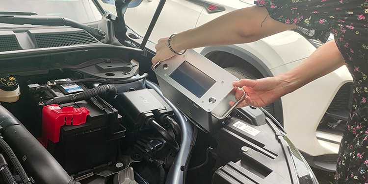
A portable VIN marking machine is usually evaluated for chassis frames, trailer beams, replacement sections and installed parts that cannot be moved to a benchtop station. Buyers comparing dot peen, scribe and laser options need more than portability: they need stable fixturing, controlled VIN data, readable depth after coating, and a traceable approval path before any permanent code is applied.
This guide covers portable VIN marking workflows for steel automotive and heavy-equipment parts, with a focus on electric or pneumatic dot peen plus the decision points that may justify scribe or laser alternatives. Legal VIN format, location, authorization and remarking rules vary by market and vehicle category, so the manufacturer, owner and responsible authority must confirm the applicable rules before any new mark or re-mark is made.
If you are comparing portable equipment for chassis and frame codes, review the VIN marking machine for chassis frames guide and send part photos, coating condition and depth requirements before choosing a fixture or sample test plan.
VIN Marking Control Plan
| Control point | Risk | Required evidence |
|---|---|---|
| Authorized data source | Wrong or duplicate VIN | Work order, database record and operator confirmation |
| Marking location | Wrong frame area or poor access | Approved drawing or work instruction |
| Head position | Skewed, shifted or interrupted characters | Fixture, magnetic base or template check |
| Part support | Shallow mark, bounce or deformation | Rigid backing and stable contact |
| Recipe | Incorrect size, force, density or spacing | Locked approved parameter set |
| Inspection | Unreadable or nonconforming mark escapes | Visual, dimensional and depth records |
Verify Authorization and VIN Data First
Before the marking head touches the part, verify the work order, part identity and authorized VIN source. Where possible, import the VIN from a database, barcode scan or controlled file instead of typing it manually. Display the full value for a second check and record who approved the job. Duplicate prevention should warn if the same value was already completed.
Manual overrides should be limited and logged. If a character is wrong, do not immediately mark over it. Stop the process, quarantine the part and follow the customer’s documented correction procedure and local legal requirements. A marking machine can create permanent evidence very quickly; software and work instructions must slow down the process at the right decision points.
Prepare the Surface and Marking Location
Remove loose rust, scale, dirt, oil or thick coating only as allowed by the approved process. Surface contamination can make the head slip, reduce dot consistency or hide the finished mark. Do not grind structural material simply to create a smooth area unless the engineering instruction permits it. Record whether the VIN is marked before or after painting, galvanizing or another coating because downstream layers affect required depth and final readability.
Use the approved drawing to locate the VIN. Check nearby welds, bends, holes, reinforcements, cables and sensitive components. The marking zone must provide enough flat or predictable surface for the character line and fixture. On a curved rail or tube, use a template or adjustable fixture that follows the geometry without allowing the head to rock.
Stabilize the Portable Head
Handheld does not mean unsupported. The marking head should locate against a rigid datum and stay fixed during the complete cycle. Depending on the part, this may use a magnetic base, chain fixture, clamp, template frame or custom locating feet. Magnets only work where material and surface conditions provide reliable holding. Paint, curvature, rust and thin sheet can reduce holding force.
Support the back of thin material close to the marking zone. Dot peen energy can cause vibration, noise, bounce and local distortion. A heavy structure may appear rigid but still resonate. Run a test on a representative offcut or approved sample to choose impact force, dot density, speed and passes. More depth should be achieved through a controlled recipe, not by an operator pushing harder on the head.
Control Character Layout and Depth
Lock character height, width, spacing, font, line direction and start position according to the approved specification. The marking window must include the full VIN with margin for fixture tolerance. Preview the layout and confirm the start edge before arming the cycle. For right-to-left access or inverted installation, use a controlled recipe instead of manually reversing data.
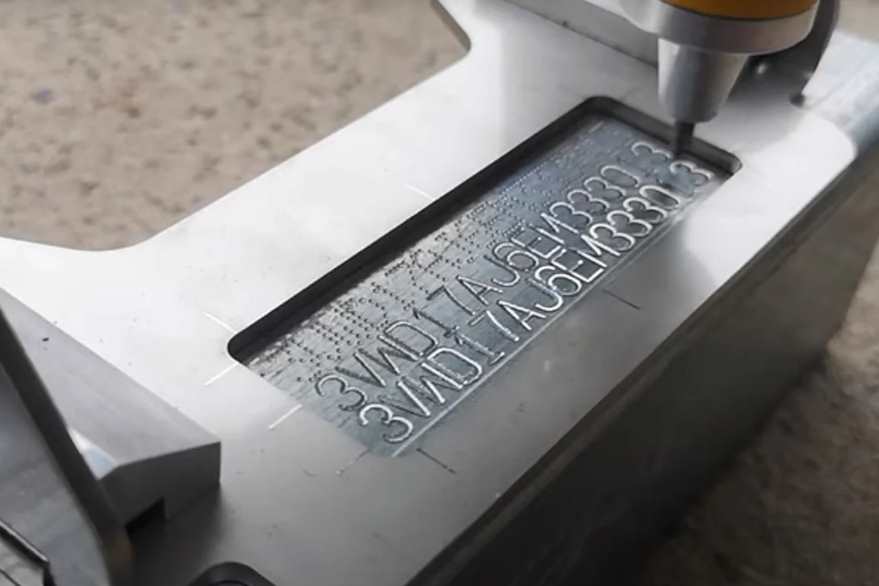
Depth depends on material hardness, surface condition, stylus, impact energy, dot density, support and number of passes. Measure depth using the customer’s approved method on samples and at defined production frequency. A mark can look dark because of surface oxide yet remain too shallow. Excessive force can raise burrs, crack a coating, distort thin material or reduce stylus life. The dot peen marking depth guide explains these variables in more detail.
Inspect Every Completed VIN
Inspection should confirm the decoded or read value against the work order, character count, completeness, alignment, location and required depth. Look for missing dots, double strikes, shifted characters, interrupted cycles and damage around the mark. If a scanner or OCR system is used, validate it against the actual font and surface; do not let automatic reading replace a defined visual and dimensional check unless the customer has approved that method.
Record the machine ID, operator, time, VIN, recipe revision and inspection result. A photo can support traceability when permitted, but the image should clearly show both the identifier and enough surrounding geometry to prove location. Protect sensitive customer and vehicle information according to the applicable data policy.
Safe Operation in the Field
Inspect cables, air lines, connectors, stylus and guards before use. Route cables so they cannot be cut, crushed, tripped over or pulled during marking. Secure the controller and power supply away from traffic, moisture and hot work. Wear the required hearing, eye and other personal protection based on the site assessment. Pneumatic systems need suitable air quality, pressure control and safe disconnection.
Establish a stable operator position. Overhead or underbody marking may require a support arm, alternate fixture or different machine format. Do not accept a workflow that depends on one operator holding a heavy head at full reach. Fatigue changes alignment and increases injury risk. For repeated production, a guided or custom fixture often produces better ROI than relying on portability alone.
Common Failure Modes
- Shallow or uneven dots: check backing, stylus condition, material hardness, force, air supply and head contact.
- Slanted character line: improve locating datums, template and start-position check.
- Double or shifted characters: stop head movement, inspect clamping and control restart behavior.
- Wrong VIN: quarantine the part, preserve records and follow the authorized correction procedure.
- Part deformation: reduce energy, add close backing, change character strategy or select another method.
- Poor readability after paint: validate depth and coating process together before production.
RFQ, Sample Test and FAT Checklist
- Provide the frame or chassis material, hardness range, thickness and coating condition.
- Provide VIN format, character size, location drawing and required depth method.
- Send photos showing access, surrounding geometry and available fixture points.
- Define database, CSV, barcode or manual data-entry workflow and duplicate control.
- Test the least rigid and hardest expected parts, not only an easy sample plate.
- Run a full VIN cycle and measure setup, marking, inspection and changeover time.
- Test power loss, paused cycle, wrong recipe, duplicate data and restart behavior.
- Approve a golden sample, fixture drawing, locked recipe and inspection record.
Review a portable electric dot peen marking machine as a starting point, then send CNMarking the real chassis photos and acceptance requirements for a fixture and sample-marking recommendation.
Frequently Asked Questions
Can a portable VIN marker be held by hand during marking?
The head should be located and supported so it cannot move during the cycle. A magnetic, chain, clamp or custom fixture may be appropriate depending on material, surface and geometry. Freehand positioning risks shifted characters.
How deep should a VIN be marked?
The applicable customer, vehicle and legal requirements determine the target and measurement method. Confirm them before purchase, then validate depth on representative material with the approved fixture and recipe.
Can I mark through paint?
It depends on the coating, required final appearance and depth. Marking before coating is common when depth must remain visible afterward, but the complete paint or galvanizing process must be tested.
What should happen after an interrupted VIN cycle?
The machine and work instruction should prevent uncontrolled restart. Quarantine the part, preserve the partial-mark record and follow the authorized recovery or correction process. Do not simply start again over the same location.
Is electric or pneumatic dot peen better for portable VIN marking?
Electric systems can simplify field setup where compressed air is unavailable; pneumatic systems may suit other depth and production needs. Compare real material, depth, portability, utilities, noise, fixture and service requirements.