
Industrial marking guide
Visual Positioning Laser Marking for Small Metal Parts
Visual positioning laser marking is valuable when small metal parts cannot be placed in exactly the same location every cycle, but the buyer still needs clean code placement, repeatable contrast and manageable operator flow. The strongest projects treat the camera, fixture, mark file and inspection rule as one production system instead of buying a vision add-on and hoping the rest will sort itself out.
This guide is written for English-language B2B buyers, distributors and process engineers who need a practical way to evaluate visual positioning on small metal parts. It covers the preparation data to collect before sample testing, the parameter boundaries that change the real process window, the operating sequence from part loading to first-article approval, the quality checks that keep codes readable and edges clean, the downtime triggers that should stop a line before scrap spreads, and the safety questions that still matter even on a well-integrated station. It avoids invented machine speeds, power claims or universal settings because those values only make sense against the real part, material and inspection rule.
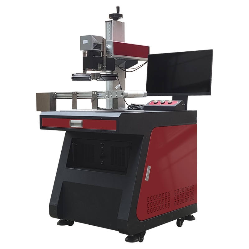
- What production facts should the buyer provide before asking for a camera-assisted marking solution?
- Which parameter boundaries matter most on small metal parts where edge distance and presentation tolerance are tight?
- How should the team run the first sample, the first approved part and the normal production sequence?
- What quality checks prove that the visual positioning route is helping instead of only adding complexity?
- Which repeated symptoms should trigger planned maintenance or downtime instead of more recipe guessing?
- When should the buyer keep fiber laser marking as the main route and when should dot peen remain in the discussion?
1. Prepare The Real Production Inputs Before Sample Testing
Small metal parts often look simple in a brochure, but they create real positioning problems in production. Parts can enter the fixture with slight rotational error, inconsistent edge contact, surface glare, oil residue or minor dimensional variation. If the buyer does not document those realities before the sample test, the marking cell may look perfect in a controlled demo and then drift when the line starts moving. The first step is therefore to describe the full production context, not just the mark size.
- List the part material, finish condition and whether the surface is raw, coated, plated, brushed, polished, oxidized or oily before marking.
- State the mark content clearly: logo, serial number, data matrix, QR code, lot code, UDI, date code or mixed content.
- Show how the part arrives at the station, including orientation drift, tray format, fixture contact points and whether an operator or automatic feeder presents the part.
- Define the acceptance rule: readable code, gradeable data matrix, visible text contrast, edge-safe placement, downstream scanning success or traceability audit requirement.
- Document whether the process needs open loading, enclosed loading, inline transfer or later integration with automatic handling.
These inputs matter because visual positioning is most effective when the team knows exactly what the camera is expected to correct and what must still be controlled mechanically. A buyer should not ask the camera to solve part wobble, unstable part height, severe glare and ambiguous code rules all at the same time. Visual positioning improves repeatability, but it still needs a disciplined part-presentation strategy.
2. Confirm Parameter Boundaries Instead Of Demanding Universal Settings
For small metal parts, the most useful technical conversation is not “what is the best setting?” but “what must stay stable for the process window to hold?” Buyers should ask the supplier to define those boundaries in practical language. This makes the process easier to hand over to operators and easier to audit when quality drifts later.
| Boundary to confirm | What the team should review | Why it matters for small parts |
|---|---|---|
| Part presentation and height | Whether the part arrives at a stable height, whether the fixture repeats reliably and whether the camera can still interpret the target when parts tilt or seat unevenly. | Small shifts become large visual errors when the mark has to stay away from edges, holes or polished cosmetic zones. |
| Camera target logic | Which feature the camera should reference: outline, hole pattern, notch, contour or predefined fiducial. | The wrong reference may look acceptable on one batch and fail when surface finish or part orientation changes slightly. |
| Mark content density | How complex the mark is, how much contrast it needs and whether the code must pass scanner grading instead of only visual inspection. | Dense codes on small parts usually leave little tolerance for location drift or inconsistent focus. |
| Surface reflection and finish | Whether the camera or operator will face glare, burrs, plated shine or mixed surface texture during normal loading. | Vision alignment and final contrast can both degrade if the part finish changes outside the approved sample condition. |
| Cycle-time pressure | Whether the line is manual, semi-automatic or inline, and whether the operator has time to reject bad placement before emission. | A process that works only when the operator pauses repeatedly may still be commercially weak in real production. |
None of these boundaries require the supplier to invent a universal number sheet. Instead, they require a sample-based approval rule, a documented fixture path and an honest explanation of what changes will force the team to retest the job. That is the right B2B discipline for camera-assisted marking.
3. Operating Steps From Sample Approval To Normal Production
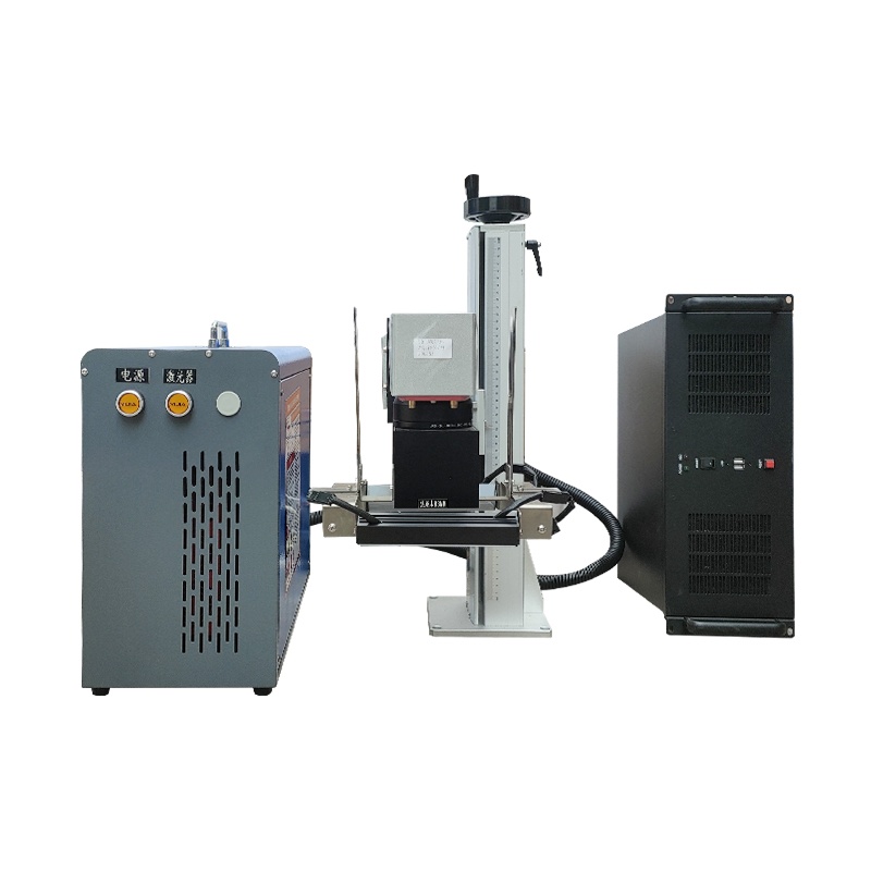
Visual positioning should simplify production only when the operator path is clear. A disciplined route starts with preparation, moves into sample approval, then into first-article release and routine production. Each step needs a clear decision point so that the team does not keep marking doubtful parts while waiting for the issue to become obvious.
Preparation
- Confirm the correct fixture, tray or conveyor nest for the current part family before loading the first sample.
- Check that the camera window, lens protection and work area are clean enough for reliable feature recognition.
- Verify that the mark file, serial logic and code format match the released production order.
- Confirm the operator can load and unload parts without forcing unstable hand positioning or shadowing the camera view.
Sample approval
- Run a controlled sample on the real part, not only on a simplified demo coupon.
- Review location accuracy relative to edges, holes, cosmetic zones and the intended reading position.
- Check the contrast, readability and scanner behavior against the production acceptance rule.
- If any part arrives with a different finish or seating behavior than the approved sample, pause and review before full output starts.
Normal production
- Release the first approved article and keep it available as the visual reference during the shift.
- Watch for camera misses, slow recognition, operator reloading habits or repeated manual corrections that were not part of the approved method.
- Check that codes remain readable and stay clear of edges as the batch changes.
- Log any recurring deviation immediately so maintenance and engineering can trace the real cause instead of blaming the last operator only.
This step-by-step route is especially important when the cell will later be expanded into an enclosed or inline format. The team should already understand the operator logic before scaling the station into a higher-throughput layout.
4. Quality Checks That Matter More Than “It Looks Fine”
On small metal parts, the mark is often tied to traceability, downstream scanning or cosmetic requirements. That means the quality check has to cover more than whether the text is visible at a glance. A strong check combines placement, contrast and downstream usability.
| Quality check | What to verify | Why buyers should care |
|---|---|---|
| Placement accuracy | Confirm the mark sits inside the approved zone and stays clear of edges, chamfers, curved transitions or functional contact areas. | Small parts often have little spare surface area, so small drift can turn into a visible defect or unreadable code. |
| Contrast consistency | Compare the first article and later parts for color shift, weak darkening, overheating or cosmetic spread. | Visual positioning only creates value if the final mark is also commercially usable and consistent. |
| Scanner or verifier result | Use the real scanner or verification route when the part requires data matrix or QR reliability. | A code that looks sharp but fails downstream is not a production-ready result. |
| Surface integrity | Check for unwanted burr response, reflectivity changes, cosmetic halo or heat-sensitive surface change near the mark. | Buyers in electronics, medical-device support or consumer-exposed components often care about the surrounding surface as much as the code itself. |
For code-heavy projects, pair this guide with the related laser data matrix marking on metal article so the team keeps verification and placement decisions connected. That is much safer than treating the camera route and the readable-code rule as separate topics.
5. Downtime Triggers, Maintenance And Repeatability Control
Visual positioning cells do not usually fail in one dramatic moment. More often, they drift through a series of small symptoms: slower recognition, inconsistent part seating, rising glare, operator workarounds, lower contrast or repeat rejects on one edge of the part family. Those are the signs that should trigger a pause before scrap or rework becomes expensive.
- Pause production if the camera begins missing the reference feature or takes noticeably longer to lock than during the approved sample.
- Stop and inspect the fixture if operators start nudging parts repeatedly to make the mark land correctly.
- Review optics, camera window cleanliness and surface-finish drift if contrast changes even though the released file is unchanged.
- Escalate repeated verification failures instead of changing the recipe batch by batch without documenting why.
- Keep spare cleaning materials and maintenance ownership clear so the station is not left in an ambiguous half-service state between shifts.
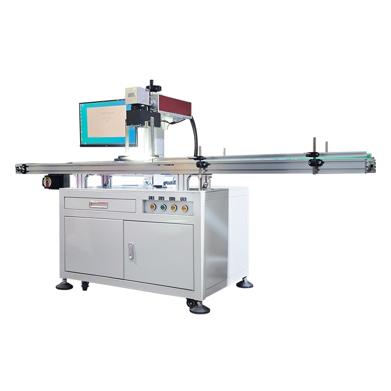
These downtime rules make the process easier to support commercially. Distributors and factories both benefit when the supplier explains which symptoms belong to routine housekeeping and which symptoms should block the next shift until the cause is clear.
6. Safety And Process Discipline Still Matter On Small-Part Marking
Visual positioning can make a station feel more automated, but that does not remove the need for controlled startup, clean loading zones, sensible enclosure decisions and disciplined operator behavior. Safety in this context also means preventing the team from creating new quality problems while trying to keep output moving.
- Keep the camera zone, fixture contact points and operator load area free of loose scrap, reflective debris or oil buildup that may confuse the visual route.
- Use guarded or enclosed layouts when the production route, operator access pattern or throughput target calls for a more controlled station; the Class 1 enclosed versus open laser marking machine guide is the right companion discussion.
- Train operators to stop when the location logic changes instead of manually compensating until the batch ends.
- Record any safety-relevant or quality-relevant visual drift in the same log so maintenance, quality and production are working from one source of truth.
- When the buyer mainly needs deeper mechanical ID on rougher surfaces, keep the dot peen marking route in the comparison rather than forcing laser into an unsuitable job.
CTA: Send A Sample And Define The Real Acceptance Rule
If your team is evaluating visual positioning for small metal parts, send the actual part photos, mark content, edge-clearance rule, scanner requirement, production rhythm and any known fixture limitations. That allows CNMarking to recommend a practical fiber laser marking route, camera logic and station layout based on the real job rather than a generic demo assumption.
Compare Fiber Laser Marking Options
Ask For A Small-Part Sample Review
Frequently Asked Questions
Does visual positioning remove the need for a stable fixture on small metal parts?
No. Camera alignment helps the system locate the real part position, but the fixture still has to control orientation, height repeatability, glare management and safe loading. Visual positioning is not a substitute for poor part presentation.
Should buyers ask for one universal laser recipe for all small metal parts?
No. Material grade, coating state, mark content, contrast target, edge condition and cycle-time pressure all change the acceptable process window. Buyers should ask for parameter boundaries and a sample-approval method, not a universal number sheet.
When should production stop and review the vision route instead of only adjusting the mark file?
Stop when the camera cannot locate the part consistently, the mark drifts near edges, contrast becomes unstable, verification grades fall, parts arrive with changed finish or the operator starts compensating manually to keep output moving.
When is dot peen still worth considering instead of visual positioning laser marking?
Dot peen can still be a better route when the part needs deeper mechanical indentation, the surface finish is less sensitive and the buyer values rugged identification more than fine contrast or compact code presentation.