Battery Pack Manufacturing for New Energy Electric Vehicles: A Comparison of Three Welding Technologies
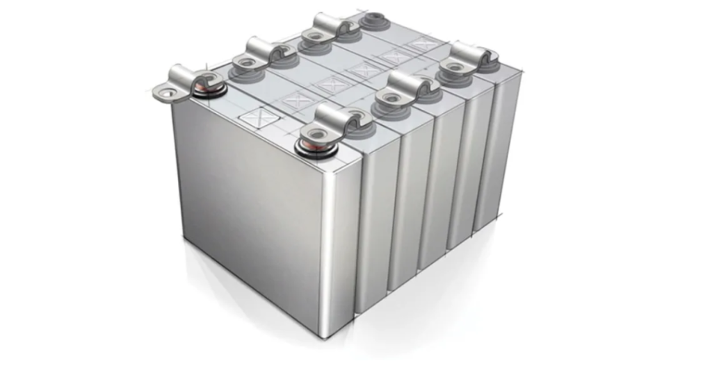
You may have already noticed the increasing number of new energy electric vehicles on the road, including cars, buses, electric bikes, and bicycles. All of these are powered by battery energy storage.
Electrification is vividly demonstrated in new energy electric vehicles, also known as e-Mobility systems , which include electric drive systems, in-vehicle information systems, communication technologies, and related connectivity technologies. One major challenge for electric vehicles is the manufacturing of batteries and battery packs.
The challenges of bringing electric vehicles to market include reducing battery weight, increasing driving range, faster charging, and lower costs. These demands translate into goals for battery design and manufacturing—batteries need larger capacity, virtually lossless energy transfer, higher charging current capacity, and the use of lighter, lower-cost materials. Furthermore, the rapid growth of the new energy electric vehicle market is placing higher demands on both the production capacity and quality of battery manufacturing.
The aforementioned goals are partly achieved through improvements in battery chemistry and battery pack design. However, achieving “zero energy loss” and “higher charging capacity” requires improving the connection quality between the battery and the conductive electrode plates (tabs).
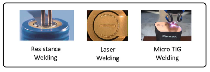
This is why special attention and care must be taken when selecting welding processes in battery pack manufacturing. In this article, we will compare three welding processes for battery tabs and discuss how to balance and choose the right one.
- Resistance welding
- Laser welding
- Micro TIG welding
Another welding process, ultrasonic metal welding , will not be compared in this article but will be introduced separately next time.
1. Five challenges in electrode welding
Five challenges in connecting electrodes and battery cells
- Welding between different metals
- Welding of thicker tab materials
- Production speed/cycle time
- Fixture design
- Process monitoring
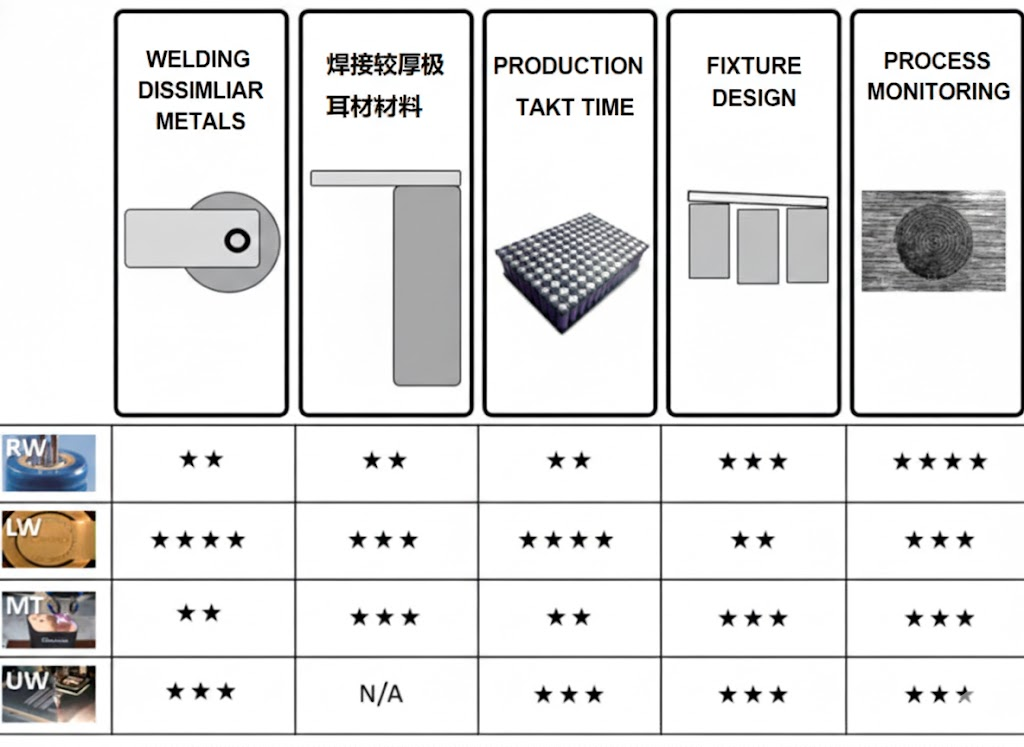
The following diagram compares four welding processes—RW (resistance welding), LW (laser welding), MT (micro tungsten inert gas welding), and UW (ultrasonic metal welding)—in the five aspects mentioned above.
2. Welding of different materials
In battery pack manufacturing, the batteries are typically already assembled, and the challenge for engineers is designing how to connect them in series or parallel to provide optimal energy output. A typical lithium-ion battery is made from nickel-plated cold-rolled steel sheets. It’s easy to weld tabs made of nickel or steel sheets onto the battery, but the problem is that both materials have high resistance.
Therefore, ideally, engineers would choose highly conductive materials like aluminum or copper for the tabs. These materials reduce heat loss and can meet the high current requirements of fast charging and discharging. However, can these different materials be joined together? Which welding process is best? Let’s take a look.
Resistance welding
The electrical conductivity of a material affects and limits resistance welding. Resistance welding requires resistance to heat and melt the parts, therefore it cannot be used for welding conductive materials such as aluminum or copper. Currently, some new alloys with both resistance and conductivity properties have been developed, such as the SIGMAclad alloy . This alloy utilizes a resistance layer for welding and a conductive layer for energy transfer.
Micro TIG welding
Strictly speaking, micro-TIG welding is a fusion welding process, which limits the materials that can be joined to chemically compatible materials. Copper and steel can be welded, but aluminum and steel cannot.
Laser welding
Generally, laser welding is a fusion welding process and also has its limitations. However, the emergence of new lasers has overcome these limitations. For example, traditional laser welding of aluminum and cold-rolled steel can result in brittle metal joints. New lasers do not have this problem, and the joints offer excellent electrical and thermal contact properties. However, as a precaution, welding feasibility testing is still necessary when choosing laser welding.
When welding aluminum tabs to batteries made of nickel-plated cold-rolled steel, the mechanical tensile strength is excellent along the vibration direction. Thermal shock tests show that the laser-welded joints meet the requirements for conductivity, strength, and durability.
3. Welding of thick tabs
Why do battery manufacturers choose thicker tabs? Because they have a higher current-carrying capacity (safely capable of handling maximum current). However, using thicker tabs means inputting more energy, and the potential for combustion and battery damage should be avoided.
Resistance welding
When using resistance spot welding, the current path between the electrode tips must be carefully considered. Electrons will always flow along the path of least resistance; therefore, as the tabs become thicker, energy will be transferred directly across the tab surface between the electrode tips, failing to reach the designated welding point. This phenomenon begins to appear on 125-micron-thick nickel tabs. To avoid current shunting, the tabs require carefully designed groove structures to concentrate and guide energy to the specific welding point.
Laser welding
During laser welding, the battery tab joint design uses a lap weld, meaning the laser must completely penetrate the upper tab and at least partially enter the battery can wall. Using a single-mode fiber laser, theoretically, it has very high penetration capability, reaching 10mm. However, in practical applications, the tab thickness is at most 0.5mm, with an optimal thickness of 0.25mm.
Micro TIG welding
The maximum electrode thickness that can be handled is 0.5mm, meeting the 200A output power requirement. However, thicker electrodes require more welding energy, which may pose a safety hazard in production.
4. Production speed/cycle time
As battery modules become larger, the demand for battery packs continues to increase. Therefore, production speed and cycle time are crucial to ensuring high-volume output. Several factors influence production cycle time, including the descent and ascent time of the drive head, welding cycle time, and the movement time of the battery welding points.
Resistance welding
During each welding operation, the electrode head first descends to contact the workpiece, and welding begins when the trigger pressure is reached. This is followed by a pressure holding phase, and finally the electrode head rises back to its original position. Additionally, the switching time between two battery welding operations must be calculated.
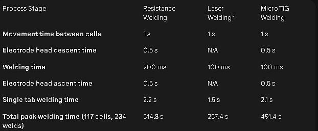
Table 1 below shows that each cell tab takes 2.2 seconds to weld. For a battery pack consisting of 117 cells (9×13), 234 tabs need to be welded, with a total welding time of 514.8 seconds.
Laser welding
Since laser welding is a non-contact welding process, the motion time includes the beam scanning trajectory and welding time, as well as the time it takes for the laser head to move from one cell to the next. For laser welding, the total time to weld 234 tabs is approximately 257.4 seconds.
Mirco TIG welding
Micro TIG welding is similar to resistance welding. However, it takes longer than laser welding, with a total welding time of approximately 491.4 seconds for 234 tabs.
Table 1 compares the time required for the three welding processes. Laser welding is the fastest and most attractive, and its welding time can be further reduced using a quasi-synchronous welding system (A Galvo Scanning System). In this case, the welding trajectory movement on the electrode is not driven by a motor, but is achieved using a mirror assembly with a small motor inside the lens.
Table 1 Comparison of cycle times for resistance welding, laser welding, and Micro TIG welding
5. Fixture Design
For successful welding, the tabs and the battery cell must be in close contact. For contact welding, the electrode head itself or the pressure head can press the workpiece firmly. However, for non-contact welding, a special fixture needs to be designed to press the welding area firmly without blocking the laser.
As battery packs become larger, fixture design needs to consider additional factors. These include cell height variations and ensuring surface flatness of the battery pack after welding. Regardless of the welding process used, the fixture design must effectively fix the welding position, not obstruct welding, compensate for component errors, and meet production capacity and lifespan requirements.
Resistance welding
The electrode head used in resistance welding can clamp the parts itself, eliminating the need for additional fixtures. For larger parts, a fixture may still be needed to clamp them at multiple points. However, overall, the fixture design for resistance welding is the simplest.
Laser welding
This is a non-contact welding process, requiring an additional fixture to clamp the parts. Generally, the clamping point needs to be close to the weld joint to prevent the tabs from deforming at the weld. Additionally, the fixture must not obstruct the laser beam.
Micro TIG welding
As an arc welding process, it is also a non-contact welding process. Like laser welding, a suitable fixture must be designed to maintain close contact between the parts. During welding, the distance between the welding torch electrode and the part is 1-3 mm, and the electrode nozzle size is much larger than the weld point, which makes fixture design quite challenging.
6. Process monitoring
Driven by the demand for higher production capacity, greater safety, and higher quality output, as well as the requirement for product traceability, process monitoring is being used more and more. The challenge of process monitoring lies in how to conduct real-time monitoring.
Resistance welding
Resistance welding processes allow for the measurement of current, voltage, force, displacement, and time. These monitoring methods are well-established. For battery pack welding, measuring collapse displacement and voltage is crucial.
Laser welding
Monitoring of laser welding has developed rapidly in the last five years. Using different types of sensors, various signals emitted when a laser interacts with matter can be detected, including reflections, heat, visible light, and ultraviolet light. During typical welding processes, the main monitoring parameters are welding energy, time, and temperature.
Micro TIG welding
Micro TIG welding monitors current, voltage, and time.
How to perform real-time monitoring? Based on the results of small-batch welding, a range can be set for each monitoring parameter, i.e., an upper limit and a lower limit. After each welding operation, the parameter is automatically compared to see if it falls within the acceptable range. If it is not within the range, an alarm is triggered to identify it as an unacceptable part.
7. Summary
We explored five challenges in battery pack welding and compared three different welding processes. Most importantly, each technology has its place in today’s battery pack manufacturing. The choice of process depends on the battery pack’s design, cost and quality requirements, and production needs.