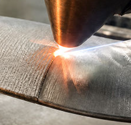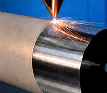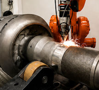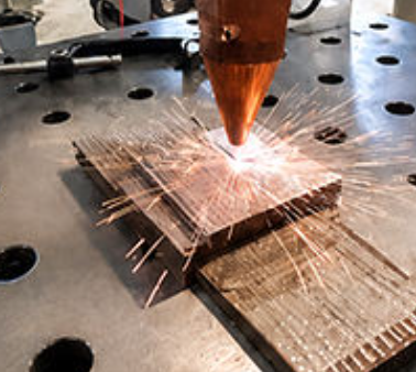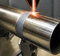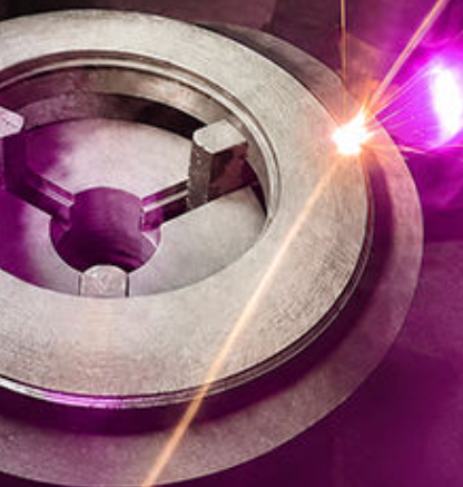
Automatic Robotic Laser Cladding System
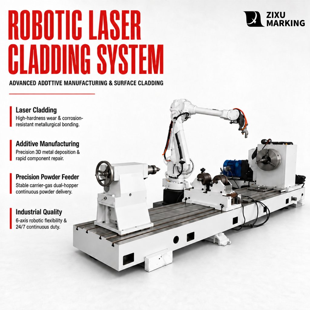
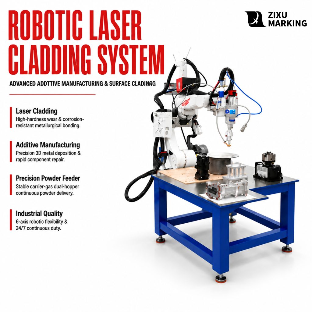
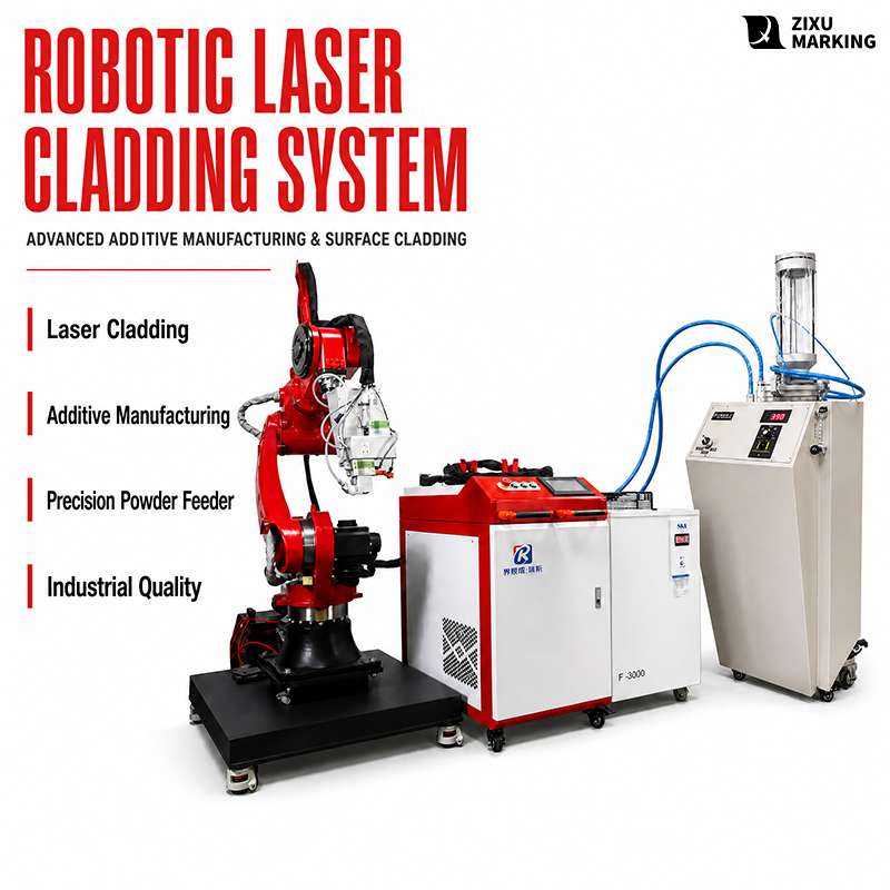
A six-axis robot with the cladding head, a seventh travel axis and positioner as standard, and cabinet, chiller and powder feeder split out: 2000 x 2000 mm envelope, 0.3-2.0 mm layers, dilution 5-8%, powder utilisation at or above 85%, eight hours continuous.
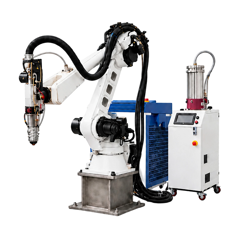
Provides a 2000 × 2000 mm working envelope, a seventh axis, and a positioner for long parts. Achieves ±0.05 mm positioning accuracy, ±0.01 mm repeatability, and 0.3–2.0 mm layer thickness with ±0.05 mm tolerance.
Operates at 10–25 mm/s with 5–8% dilution, powder utilization ≥85%, and coating porosity ≤1%. Adjustable parameters balance cladding speed, layer thickness, and coating quality for different parts.
Features ≥40 kW installed power, 380 V three-phase input, and 220/440/480 V options. A dual-temperature chiller independently cools the laser source and head, supporting 8+ hours of continuous operation.
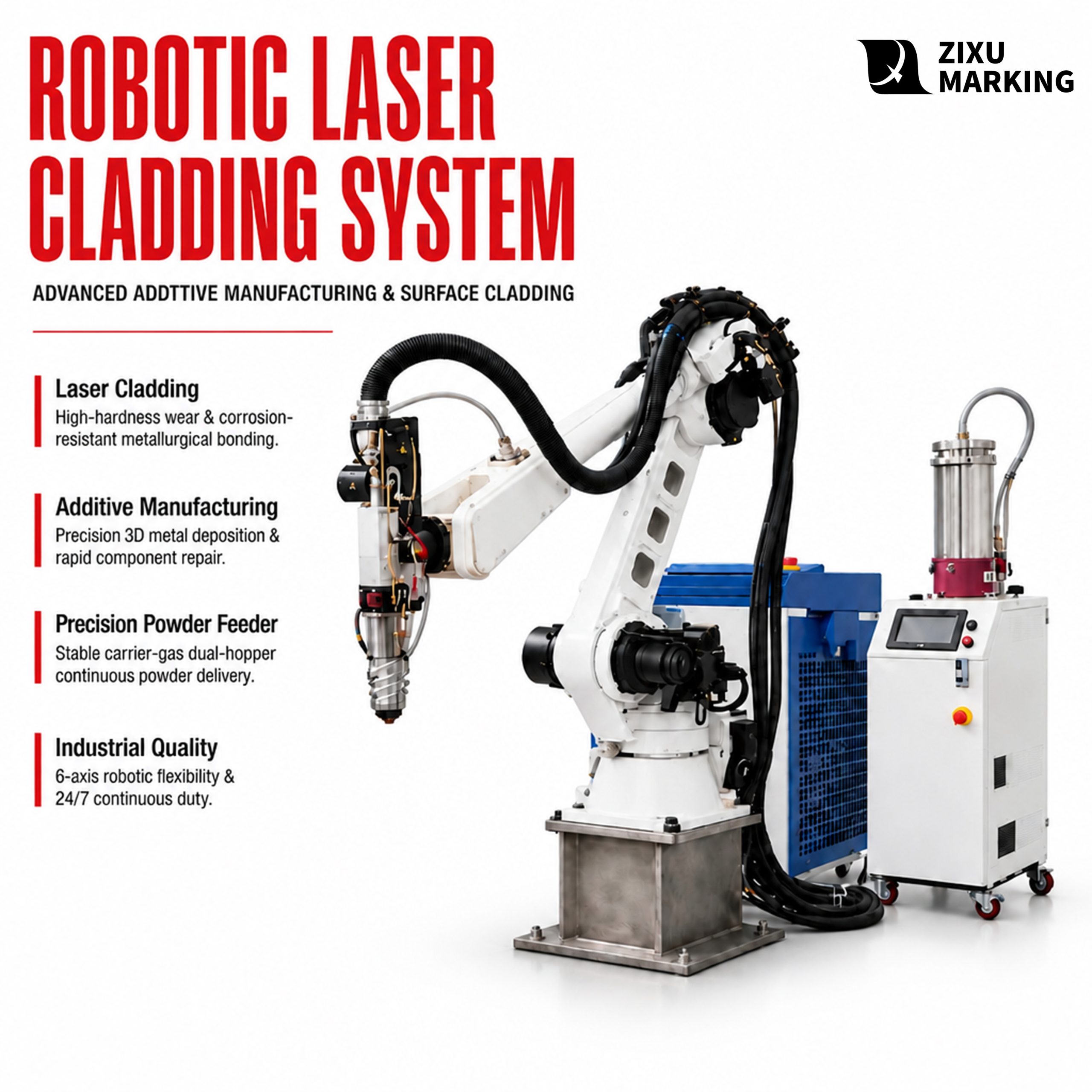
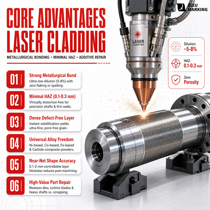

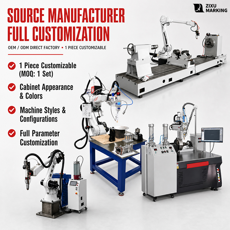

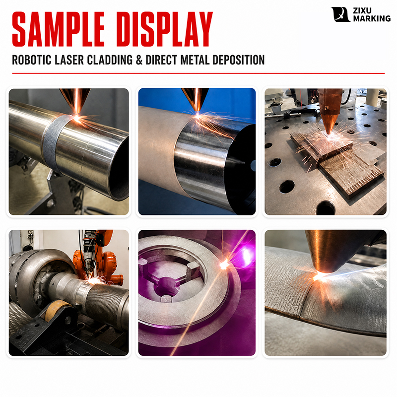
The cell is a 6 kW fibre laser cladding system: a six-axis robot on a seventh travel axis with a positioner, carrying a coaxial powder cladding head, with cabinet, chiller and feeder sited separately. Its 2000 x 2000 mm working envelope takes hydraulic rods, shafts, rolls, dies and valve seats that no lathe can hold in one setting. The deposit is where the saving sits: single layers of 0.3-2.0 mm at 10-25 mm/s, layer tolerance +/-0.05 mm, dilution 5-8 percent, powder utilisation 85 percent or better, porosity at or below 1 percent, and a metallurgical bond that carries impact and wear without lifting. Positioning accuracy is +/-0.05 mm and repeatability +/-0.01 mm, so a worn journal returns to drawing rather than to a machinist’s judgement. Eight hours of continuous work is held by a dual-temperature chiller on 40 kW of installed power. Typical use is remanufacture and surface hardening – worn rods and journals rebuilt, roll faces and mould cavities restored, valve seats re-faced, in the workshop or at the machine.
| Category | Parameter | Unit | General baseline (6 kW standard) |
| A System | Structure | – | 6-axis industrial robot + 7th travel axis + positioner + cladding head + cabinet / chiller / powder feeder (split) |
| A System | Working envelope (robot reach) | mm | 2000 x 2000 (turning radius approx. 1813) |
| A System | Installed power | kW | >= 40 (laser + chiller + robot + auxiliaries) |
| A System | Power supply | V / Hz / phase | 380 V / 50-60 Hz / 3-phase (220 / 440 / 480 V built for destination) |
| A System | Positioning accuracy | mm | +/-0.05 |
| A System | Repeatability | mm | +/-0.01 |
| A System | Cladding accuracy (layer tolerance) | mm | +/-0.05 |
| A System | Cladding linear speed | mm/s | 10-25 (with powder) |
| A System | Single layer thickness | mm | 0.3-2.0 |
| A System | Cladding rate (area) | m2/h | 0.3-0.8 (empirical range, to be proven on the sample) |
| A System | Dilution | % | 5-8 |
| A System | Powder utilisation | % | >= 85 (coaxial feed) |
| A System | Bond | – | Metallurgical (not the mechanical bond of spraying) |
| A System | Coating porosity | % | <= 1 |
| A System | Continuous working time | h | >= 8 (with dual-temperature chiller) |
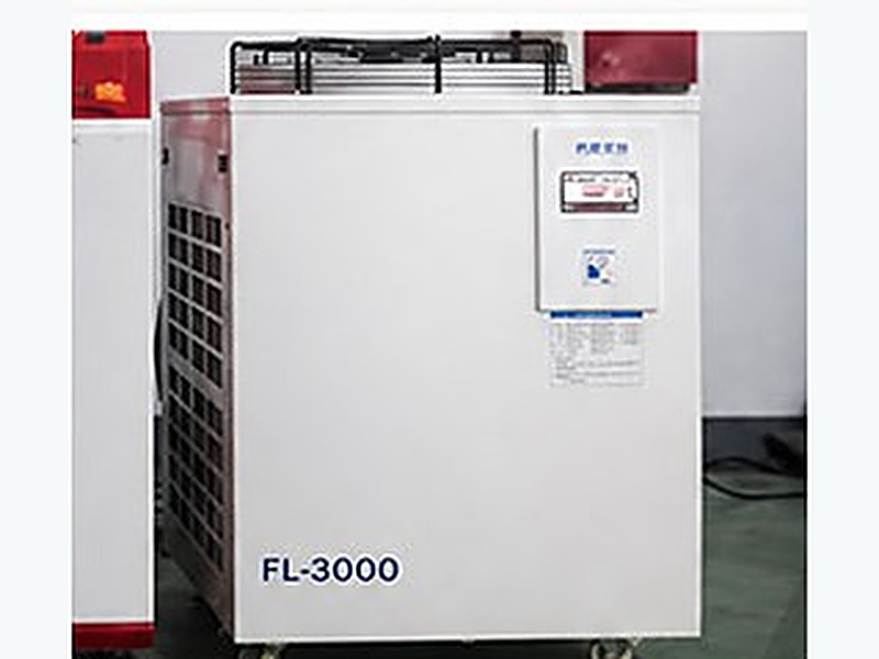
Industrial water chiller FL-3000: constant temperature is the floor under continuous work
The chiller is an FL-3000, constant-temperature refrigeration, with a temperature display and alarm-code chart on the panel. Cladding is a long, high-heat-load process: when water temperature drifts, the head optics distort first, then the source output follows, and what reaches the part is a layer that thins from piece to piece. This cell uses a dual-temperature chiller, with source and head on separate circuits, for eight hours or more of continuous work.
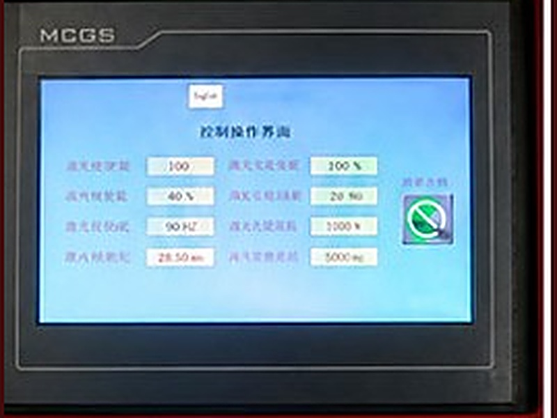
MCGS touchscreen: the parameters live on the screen, not in the operator’s hands
An industrial touchscreen (MCGS) shows the whole recipe on one page – laser power and frequency, powder feed rate, feed gas and carrier gas flow, shielding flow, powder pre-feed and delay – with one-touch start and stop. Recipes are stored in the cabinet, so a changeover is a recall rather than a re-teach: batch consistency comes from the machine, not from whoever is on shift.
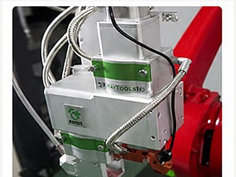
RayTools cladding head: a tight spot is what keeps the heat-affected zone narrow
The head is a RayTools unit, water-cooled with its own protective lens seat, powder and gas entering from the side, and a spot that closes down small. Low beam divergence is what concentrates energy on the toolpath: dilution of 5-8 percent and layers of 0.3-2.0 mm are held here, not in the software. A narrow heat-affected zone is also what makes thin-wall and heat-treated parts repairable at all.
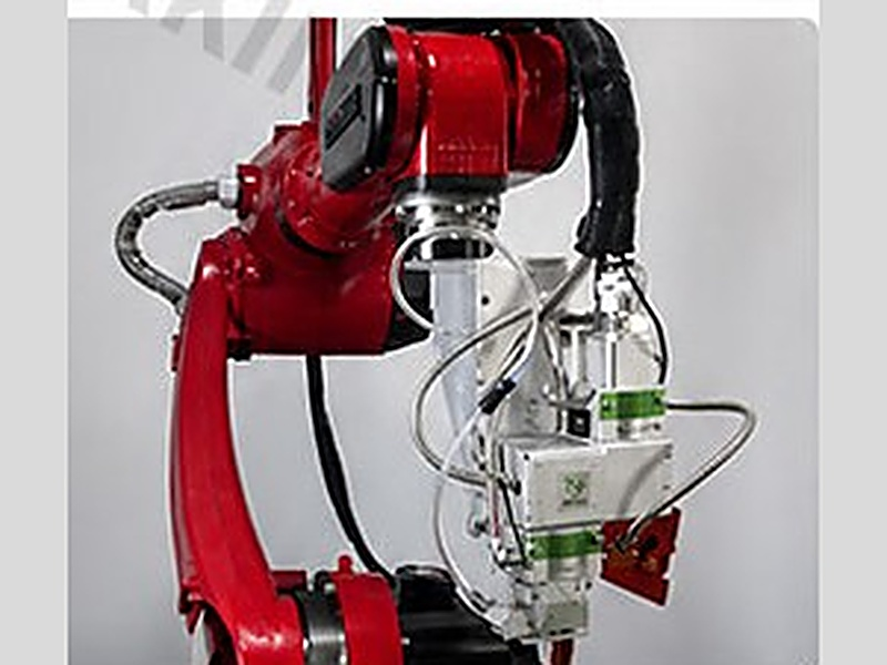
Six-axis industrial robot: reach and the ability to come back to the same point
A six-axis arm carries the head, working with a seventh travel axis and a positioner over a 2000 x 2000 mm envelope at a turning radius of about 1813. Positioning accuracy is +/-0.05 mm and repeatability +/-0.01 mm. The three numbers answer three different questions: where the torch goes, whether it returns to the same place, and whether a 0.3-2.0 mm layer comes out the same on the second pass. Shafts can be indexed as they are clad, so long parts need no re-chucking.
Available Models
Material and Workpiece Fit
Power and coating are starting points. Sample every new material: most cladding failures come from cleaning and preparation, not parameters.
| Workpiece/substrate | Typical failure | Deposit | Process note |
| Hydraulic rods (45#, 27SiMn) | Scoring, eccentric wear, chrome spalling | Ni self-fluxing / Ni + WC | Build in 0.3-2.0 mm layers; grind to Ra 0.2 after cladding |
| Rolls | Surface wear, heat checking | Cobalt-based / Ni + WC | Interpass temperature on large areas; count passes at the 2.0 mm ceiling |
| Shafts and gears | Journal wear, pitting | Nickel-based | Single teeth on fine-pitch gears, not the full circle |
| Dies (die-cast, forging) | Heat checking, edge collapse, wear | Cobalt-based / Ni + WC | Temper after cladding on hot-work dies |
| Valve seats | Erosion, cavitation | Cobalt-based (Stellite type) | Machine after cladding; never leave as-deposited |
| Mining and earthmoving wear parts | Abrasive wear | High-chrome / WC composite | Layer-thick sections, none above 2.0 mm |
| Petrochemical and nuclear | Corrosion, pitting | Nickel 625 / C-276 class | PT and degrease first; oil means porosity over spec |
What this cell should not be quoted for
| Workpiece / condition | Why not |
| Thin wall (under 1.5 mm) | Even low heat input collapses it – use laser welding or micro-plasma |
| Grooves deeper than 2.0 mm in one pass | Must be layered, and every extra layer costs efficiency and price |
| Aluminium and copper substrates | High reflectance and conduction give a narrow window – validate before promising |
| Nitrided or chrome-plated surfaces | Strip first, or the deposit debonds |